copied from http://funofdiy.blogspot.co.uk/2013/10/a-raspberry-pi-controlled-mini-laser.html
A Raspberry Pi controlled mini CNC Laser engraver
I recently made a mini CNC laser engraver using two DVD drives salvaged from old computers and <$10 extra parts bought on eBay. The controller of the CNC machine is a Raspberry Pi, a $35 credit card size computer. The engraver turns out to be pretty successful. So I am sharing it with everyone.
There have been a lot of examples people using Arduino to control CNCs. And you can probably can find tons of C programs available that can run directly on Arduino to process G code. A famous one is grbl. Like this on by Groover in instructable A Chinese translation can be found here. Also there are available CNC controller like MATH3 on the market that can be controlled by serial.
I am taking a different approach by using a RPi (http://www.raspberrypi.org/)
The reason why I choose Raspberry Pi is: it is a much more powerful device than Arduino; it has a complete OS; the GPIO pins can be controlled by python, a more intuitive and simpler language than C (the disadvantage of python would be the slow speed); I don't have to buy a separate controller for this project--I can use a single Raspberry Pi to do a lot of different things withoutreloading firmware. Most importantly, I have a Raspberry Pi but don't have an Arduino right now!
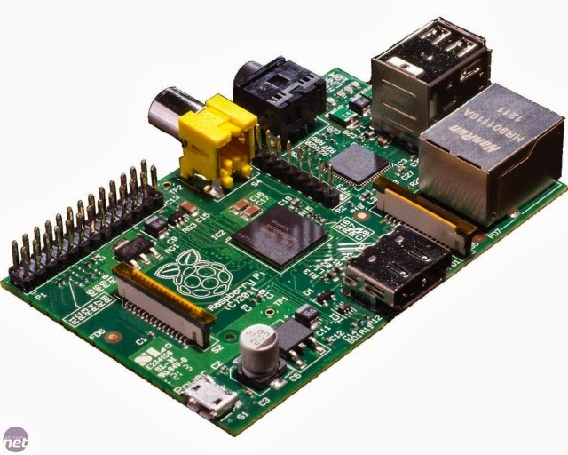 |
| A Raspberry Pi mini computer |
Also, there are projects people running LinuxCNC on Raspberry Pi and use an external PIC 32 board to control CNC. It's a great idea but I want to limit my cost to be minimum. Instead, I wrote my own python interpreter to execute G code or process jpg image directly. For 2D CNC laser engraver, it is actually very easy to control and don't require high-level program techniques.
I will keep updating this post. And hopefully this post will eventually cover everything including the python code.
First, some pictures.
 |
| Laser engraver is working |
 |
| A coin size university icon on a plastic board |
 |
I messed up the direction for this one...
|
 |
| Some words.. |
 |
| The machine is not packaged yet. You can find: machine (top middle), controlling circuit (top left) and RPi (lower right) |
 |
| The controller and wires in a perfect chaos |
Must read!!!
This post has drawn considerable attention in the past several weeks. Sorry that I still haven't been able to finalize it yet.. But everything needed to make a RPi mini laser engraver is already here. Once all parts are ready, it shouldn't take more than a weekend to finish the project.
Now, as everyone does, I feel crazy about laser. But it is extremely important to keep in mind that the laser used in this project could burn human eye retina in millisec before eyeball is capable to react. Even a random reflection beam during engraving could be >50 mW (for comparison, a regular laser pointer is 1 mW), and make permanent damage to your eyes, kids' eyes, or pets' eyes. ALWAYS WARE A LASER SAFE GOGLE when you are close to the working engraver. A suitable one for 650 nm laser should be green color. MAKE SURE THE ENGRAVER IS NOT ACCESSIBLE TO KIDS OR PETS. I would suggest everyone planning to build this should enclose the whole thing inside a large box or cover (however, mounting a little computer fan on the box would be nice).
AGAIN, think TWICE before you make it.
About the capability of the engraver
Due to the size limit of DVD drives, the machine can only engrave within an area of 36 mm by 36 mm.. So it can do little pieces of wood, plastic board or iPhone cases, but not any larger.
The laser used here is 200 mW 650 mm red laser diode. It cuts letter paper fine. But It is not powerful enough to actually cut through anything thicker and tougher. In fact, the working surface is preferred to be black color so that it can absorb as much laser power as possible. To engrave on transparent plastic board, as shown above in the coin size university icon picture, I have to use a black marker to paint the surface and clean the ink after engraving. However, I believe for a thin black foam sheet (<3mm thick), and given enough engraving time, the laser should be able to cut it through, as Groover showed in instructable.
Now here is the instruction.
Things required:
1. A raspberry pi (running Raspbian or what ever supporting GPIO)
Things required:
1. A raspberry pi (running Raspbian or what ever supporting GPIO)
2. two DVD writable drives.
To be able to engrave, you need 200mW laser diode from DVD writer. A DVD R or CD R will do nothing. A CD writer might be OKin term of power (~100mW), but the laser diode of a CD writer is infrared, which can be super dangerous (you can't see it!).
3. a TO-18 5.6mm laser housing
(like this one http://www.ebay.com/itm/251316903193?ssPageName=STRK:MEWNX:IT&_trksid=p3984.m1439.l2649)
4. Two dual channel H-bridges.
A H bridge is a circuit containing four (effective) switches that can apply a voltage across a load (DC motor or one coil of a stepper motor) in either direction.
Stepper motors from DVDs are 4 wire 2 phase bipolar stepper motors. They require truly reversible voltage on each pairs of the wire. You need two H bridges for each stepper motors. So total of four H bridges for teo strepper motors. Some famous stepper motor controllers like ULN2003 are for the 5 wire stepper motors, so they cannot be used for controlling the DVD stepper motors.
You can make your own H bridges by using 4 NPN and 4 PNP transistors and probably TTL converters (RPi's GPIO pin are 3.3V so logic TTL chips might be required). Or you can simply buy them. There are a lot of integrated H bridge circuits available in the market, such as L298. The ones I use are L9110s Dual H Bridge purchased on Ebay (like this one: http://www.ebay.com/itm/350877288713?ssPageName=STRK:MEWNX:IT&_trksid=p3984.m1439.l2649). They are low cost (~$2 each), compact (.8"x1") and are powerful enough (~800mA). However, if you buy from a Chinese seller, shipping can cost 3 weeks.
L9110s is also known as HG7881.
Regarding the H bridge, you need to make sure that the continuous current limit of the circuit is greater than 500mA. Usually the stepper motor in a DVD drive is rated at 5V and each coil has a resistance of 10ohm. So the current through each coil would be 500mA!
5. a LM317 regulator, a power NPN bipolar transistor (like E3055, should be able to handle continuous 200mA at least), some resistors, capacitors and a bundle of jumpers.
The LM317 is for the laser driver. The power NPN is for making a switch for the laser. My lab has tons of these components so I don't have buy them. If you don't want to solder a driver by your own, you can surely buy a laser driver for <$5. The laser driver need to be able to output at least 200mA at 2V and have the function of enable/disable.
6. a solder gun, screw driver and some basic hard wares.
STEP 1: Disassemble DVD drives
There are a lot of picture/video tutorials online for this step so I will keep it short.
 |
| Two DVD found in E-waste |
 |
| They are rewritable |
All you need from the DVD are
1. stepper motor with the slider (lower right part in
the picture below)
 |
| tearing down a DVD |
2. Laser diodes (see picture below). Be very careful
that the laser diodes on the DVD are very fragile.
Make sure you don't break them.
 |
| Two 5.6mm laser diodes (infrared and 650nm red) compared with a USB connector. |
 |
| Stepper motor (right) and linear slider. I soldered four wires on the stepper motor. |
There are other good things you can salvage from the DVD drive and keep for future projects, such as a 9 V dc motor near the gate, a brushless motor that spins the DVDs, some shock reducers and some miniature lens and optic parts. You can also find four strong magnets near the laser diode. Don't throw them away. They will turn out to be useful later.
STEP 2: Assemble Laser
Now you have two laser diodes. One is infrared which we don't need. The other one is 650nm red diode (usually has a letter 'R' on it) and is the one we need. The diode normally has three pins forming a fat triangle. One is NC. You need a multimeter to figure out which two pins are cathode and anode. The forward voltage across anode and cathode should be around 1.4V and the forward resistance should be 20-40k ohm. If the forward resistance is too high then the laser diode is over used. |
| The laser diode housing |
 | |||||
| Laser diode (middle left) and laser housing |
 |
| Pushing the diode into the housing head |
 |
| Laser diode in the housing head |
 |
| Solder two wires on the diode |
 |
| Use some heat shrink to increase the strength |
 |
| Getting there |
 |
| Done! |
Carefully put the laser diode into the head of the laser housing. You can use the laser housing body to help knock against the diode and push the diode into the housing head. The diode should fit perfectly into the head. Make sure the pins are still fine. Then solder two wires to the electrodes and assemble the housing together.
STEP 3: Make laser driver and enabler and test the laser
A laser diode is like a photodiode but equipped with a resonant cavity. Laser diode is a huge current sink. Once the diode conducts, it generates a lot of heat, and the heat further lowers the diode impedance. So it is a unstable positive feedback system. If you simply put a 1.5 V battery across the diode, you will either get the diode burn or battery drained right away. We need a laser driver that can output a constant current to the diode.
There are numerous way to do this. One of the most popular and least frustrating way is to use a DC current regulator. LM317 is a good choice. By adding a resister R across the adjust pin and output pin, LM317 can output a constant current of ~2V/R.
A good instruction can be found here LM317 Laser Driver

In my case, I replace the two parallel 10 ohm resistors by two .5 Watt 12 ohm resistors. The max current I am going to run through the diode is 200mA.
Make sure you don't mess up the adjust pin and the output pin. A heat sink would be necessary on the LM317.
You also need a switch that can be controlled by RPi. I used a power NPN E3055 transistor. You can choose what every you want, just make sure that the transistor can support continuous CE current >300mA and also put a heat sink on it.
 |
| Schematics of the laser driver and the switch. Laser is on only when "Laser switch" port is logic high (>3V). Make sure you don't mess up the pin order of LM317 |

LM317 Laser driver


Laser driver (top) and the E3055 power NPN (bottom)

STEP 4: Shape the machine
Now you have two identical linear stages and it is time to put them together! There are a lot of ways to do this. For 2 axes CNC machine, I think the best way is the one given by Groover @ instructable. In Groover's configuration, the engraving sample is attached to x-axis so it only moves in x direction. The laser is attached to y axis so it only moves in y direction. This configuration minimizes the weight on each of the axes. |
| Laser engraver I made |
I cut a 2"x2" steel board out of the DVD case and glued it to the x-axis stage as the sample support base. Since the DVD case is made from iron, you can use the strong magnets salvaged from the laser optical system to help you stabilize the engraving sample on the base.
The laser diode will generate a lot of heat . And it is important to dissipate this heat. Otherwise the diode will die fast. I cut a 1inch cube heat sink from an old computer CPU heat sink and drilled a hole though it. The hole is perfectly large to hold the laser. I glue the heat sink on the y axis stages.
The most important issue is the x axis, y axis and body of laser have to be perpendicular to each other.
STEP 5: Connect H-Bridge to the stepper motors
 |
| Four connect pins on a 4-wire-2-phase stepper motor. They are usually arranged in the following order: a1,a2,b1,b2. (a1 and a2 are the two leads of coil a; b1 and b2 are the two leads of coil b). Using a multimeter will help to verify this. |
Here is a very good tutorial on Bipolar stepper motor Bipolar Tutorial
 |
| Conceptual model of 4-wire 2-phase stepper motors, from Bipolar Tutorial.I renamed the pins |
Seems I am using different names for pins of stepper motor. In most people's writeup I can find online, they define coil 1 and coil 2 and name 1a, 1b as the two leads of coil 1, and 2a, 2b as the two leads of coil 2. It doesn't matter, as long as we know what we are doing. At least in this post I will keep the terminology thing consistent.
The central spinner of the bipolar stepper motor can be regarded as a bar magnet (actually it is circular). Obviously from the figure above that if we successively conduct current in coil a1, b2, a2 and b1, the spinner will spin in the desired sequence. To do this, we can apply a voltage sequence to a1, b2, a2, b1 as:1) high, low, low, low. So only a1 and a2 are activated. Since a1 a2 have same polarity (or opposite depending on how you define it), the spinner is pointing to a1
2)low, high, low, low. So only b2 and b1 are activated. Spinner is pointing to b2
3)low, low, high, low. So only a2 and a2 are activated. Spinner points to a2
4)low, low, low, high. Spinner points to b1.
go to 1).
Denote high as 1 and low as 0. The sequence can be written as 1000,0100,0010,0001
The advantage of this configuration is that it is very easy to understand and usually the stepper motor moves very precisely. However, since in each step only one pair of coils is activated, the torque applied on the spinner is not very great.
To achieve high torque, a more popular way is to apply the following sequence: 1100,0110,0011,1001. And the spinner will be pointing to middle of a1 and b2, middle of b2 and a2, middle of a2 and b1, middle of b1 and a1 consequentially. And the torque is doubled. This is called full-step mode or high torque mode or two phase mode.. and is usually the mode used.
If the torque won't be a problem then we can use a 8-step sequence: 1000,1100,0100,0110,0010,0011,0001,1001. The spinner will turn 8 steps instead of 4 steps to turn same angle. This doubles the resolution. And the cost is the non-uniform torque being applied on the stepper motor. This is called half-step mode.
Usually for DVDs, the linear sliders moves about 0.15mm every full step stepper motor turn, corresponding to a resolution of ~170dpi. Good enough for home-made projects. If 8-step mode is implemented, then the resolution is 0.075mm/step or 340dp, similar to regular printer.
For laser engraver, there isn't any serious load on the stepper motor so I choose the half-step mode or 8-step mode.
As mentioned, RPi cannot drive the stepper motor directly because of the current limit. Actually, besides powering low power LEDs, the GPIO pins of a RPi usually serves as logic switches. In output mode, they are either logical High (3V) or logic low (<0.7V). A H bridges is a "translator" that translates these logic High or Low into power source that has high voltage or low voltage.
 |
| A conceptual schematics of H bridge (from wiki) |
 |
| A very simplified conceptual schematics of NPN PNP H bridges. Make sure you don't build an H bridge based on this graph. You will probably burn the transistors or even the Pi. A practical H bridge requires current limiting resistors, reverse diodes and logic TTL chips. Please consult more from other sources if you would like to build a working H bridge from scratch. |
When A is logic low (0V) and B is logic high(+V), then transistor 1 and 4 are conducting while 2 and 3 are open; when A is logic high (+V) and B is logic low (0V), then transistor 1 and 4 are oepn while 2 and 3 are conducting. When both A and B are logic high, 2 and 4 are conducting, 1 and 3 are open, the motor stalls; when both A and B are low, 1 and 3 are conducting, 2 and 4 are open, the motor stalls.
Therefore by setting A and B high or low, we can control the current direction through a load. For each 4 wire 2 phase stepper motor, there are two independent coils we need to control. So a total of 4 H bridges are required to control the two stepper motors.
There are a lot of integrated H bridge available on the market. For my case, I need 500mA through each H bridge so L9110S suffices (L9110S can afford 800mA through each H bridge). Each L9110S contain two H bridge so two of them is enough. There are L9110S module for <$2 each on the market. Very convenient!
I am not exactly sure but I think sometimes people call it L9110 sometimes L9110S.. Datasheet can be found here.
Also, L9110S has internal clamp diodes to conduct the reverse current generated by the sudden stop of the stepper motors. This protects the circuit. L9110S is TTL/CMOS output level compatible so it can be directly connected to RPi.
 |
| Two L9110 dual H bridges (also known as HG7881). They are 0.8" by 1" big Each dual bridges control a stepper motors. On the right hand side, there are a1, a2, b1, b2 connectors to the stepper motors (top to bottom). On the left hand side, there are logic control pins for a1, a2, b1, b2 (actually they are named as A-IA, A-IB, B-IA, B-IB) and VCC and GND. |
 |
| When powered, the chips light up (The big circular thing is my ring. I don't have a big finger..) |
STEP 6: Driving the machine using Raspberry Pi
Now this is the key part. Because I am not using external stepper motor drivers so I have to incorporate the function of external stepper drivers in software. I choose python to do the job.People say that RPi is not a real time device because it has an entire OS on it and python is very slow. However, in my case, these issues didn't cause any trouble.
The python code I wrote includes the following functions:
1. An encapsulated bipolar stepper motor class. It enclosed information like phase and position. It has a .move(direction, steps) build-in function that converts movement commands into a sequence of GPIO.output() commands that spins the stepper motors.
2. A G code interpreter: read G code and send the corresponding commands to the bipolar stepper motor objects. For G02 and G03 commands (circular interpolation), the interpreter performs the interpolation and converts the commands into a sequence of straight motions.
The most challenging part is how to control more than one stepper motors simultaneously. The idea is actually very simple and can be extend to any number of motors. We know that how to control each individual motor. Now suppose we have two motors, MX and MY and we want to turn MX 12 steps and MY 15 steps simultaneously in 6 seconds. First find the least common multiplier (LCM) of 12 and 15, which is 60. Now divide 6 seconds by 60 we get dt=0.1sec. Set 60 loops. Before the end of each loop, we use time.sleep(0.1) commands. So it takes 6 sec to finish the loop. And we move MX one step every 5 loops and move MY one step every 4 loops. After 60 loops, MX moves 60/5=12 steps and MY moves 60/4=15 steps. And both MX and MY moved at constant speeds.
0000100001 0000100001 0000100001 0000100001 0000100001 0000100001 (60 digits, 12 ones)
0001000100 0100010001 0001000100 0100010001 0001000100 0100010001 (60 digits, 15 ones)
For more than two stepper motors, just find the LCM of all the steps (ignore 0).
You can download all the python code here My RPi CNC Laser Engraver Code:
You can find three python codes:
Project: raspberrypi-cnc-laser-engraver
| Code | Uploaded by | Date | Language |
|---|---|---|---|
| Bipolar_Stepper_Motor_Class.py | Xiang Zhai | October 25, 2013, 11:34 pm | python |
| Motor_control.py | Xiang Zhai | October 25, 2013, 11:38 pm | python |
| Gcode_executer.py | Xiang Zhai | October 25, 2013, 11:39 pm | python |
|
Bipolar_Stepper_Motor_Class.py defines the Bipolar_Stepper_Motor class. By default, line 5 is commented and line 7 is valid. This corresponds to a 8-step half-angle sequence. If maximum torque is desired, you can comment line 7 and uncomment line 5 to select 4-step full-angle sequence.
Motor_control.py defines a set of functions such as LCM (for calculating the lcm of two integers) and Motor_Step (for controlling two motors simultaneously). Usually you don't need to modify anything.
Gcode_executer.py
This is the main program. You need to modify line 25 (G code file name), line 29 (pin numbers for stepper motor X), line 31 (pin numbers for stepper motor Y), line 32 (pin number for laser switch), line 35, 36 (resolution of the machine in unit of mm/step) and line 38 (engraving speed). The code read and interpret G code, and send corresponding commands to the motor control functions.
spiral.nc
This is a simple G code which plots a small spiral. It can perfectly test whether the machine can process G code, especially the circular interpolation G02 and G03, correctly.
grid.nc
A simple G code which plots several straight lines to make a grid. Perfect code to test the machine and make a coordinate system!
Currently the Gcdoe_executer.py only accepts limited number of G commands: G90, G20, G21, M05, M03, M02, G01, G02, G03.
The code can recognize G1F commands (engraving speed) but simply ignore it. Engraving speed is set by line 38 in unit of mm/sec.
STEP 7: Engraving!
Following Groover, I use Inkscape to make G code. Inkscape is an open-source vector graphics editor and support various OS (windows, linux, Mac), which means that you should be able to install it on Raspbian! I didn't try that. I simply use my laptop and send my design to the RPi.
You need a laser engraving extension to convert the vector graph into G codes. There are several different G code extension. The one I use can be downloaded here Inkscape-Laser-Engraver-Extension
I should have included more instruction on how to do this but I am a little bit too busy these days. Essentially I followed the instruction by Groover in instructable. When I get enough spare time I will work on this section more~
No comments:
Post a Comment